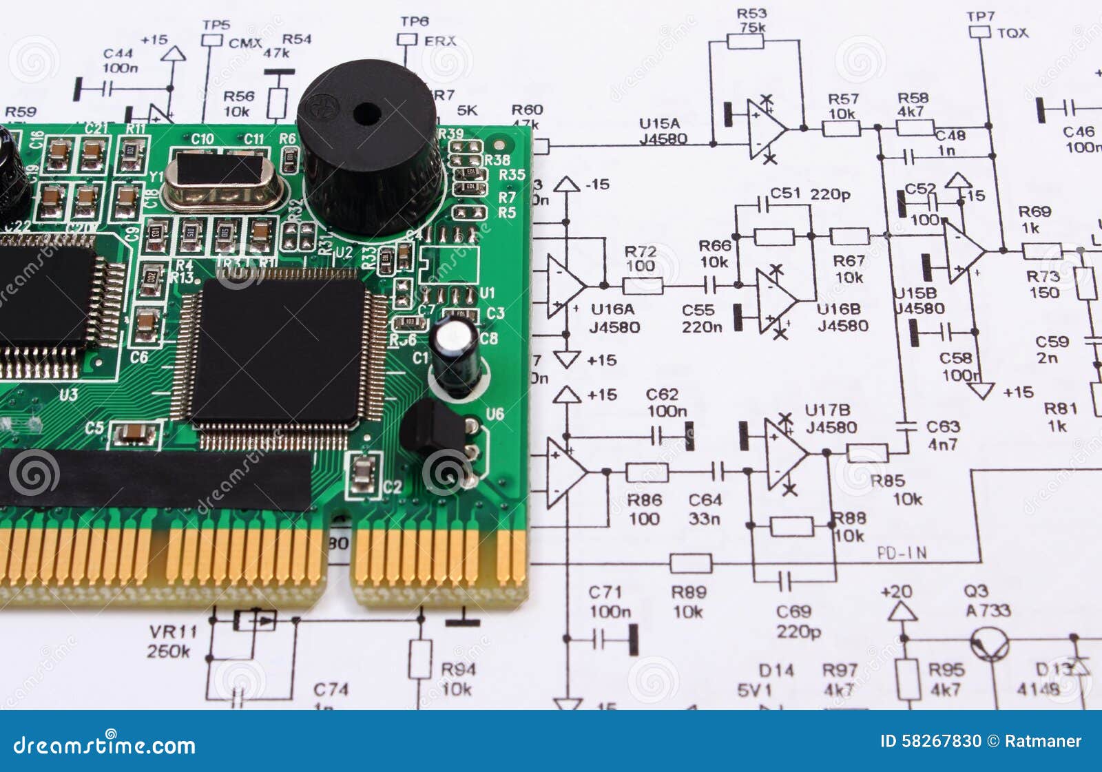
Circuit Board With Diagram. And the core components of these schematic diagrams are unique circuit symbols that all designers globally can understand. We'll go over all of the fundamental schematic symbols:. a circuit board schematic is a visual representation of the electronic circuitry that is used to design and. by understanding the basics of circuit board components, reading schematics, and using tools like magnifying glasses and multimeters,. in this instructable i will talk about how to read a schematic and how to identify electrical components on a pcb (printed circuit board). Over the next few pages,. So knowing these schematics is paramount. this tutorial should turn you into a fully literate schematic reader! Electrical components are identified two main ways. the circuit board components diagram provides a clear and organized representation of the various components. a pcb schematic is a circuit diagram designers use in the first stage of the board design process. And we will look at how to read pcb schematics in this article to get you started. this tutorial will breakdown what makes up a pcb and some of the common terms used in the pcb world.
from dreamstime.com
a circuit board schematic is a visual representation of the electronic circuitry that is used to design and. So knowing these schematics is paramount. Electrical components are identified two main ways. a pcb schematic is a circuit diagram designers use in the first stage of the board design process. this tutorial should turn you into a fully literate schematic reader! And we will look at how to read pcb schematics in this article to get you started. by understanding the basics of circuit board components, reading schematics, and using tools like magnifying glasses and multimeters,. the circuit board components diagram provides a clear and organized representation of the various components. this tutorial will breakdown what makes up a pcb and some of the common terms used in the pcb world. We'll go over all of the fundamental schematic symbols:.
Printed Circuit Board Lying On Diagram Of Electronics, Technology Stock
Circuit Board With Diagram this tutorial will breakdown what makes up a pcb and some of the common terms used in the pcb world. a circuit board schematic is a visual representation of the electronic circuitry that is used to design and. the circuit board components diagram provides a clear and organized representation of the various components. by understanding the basics of circuit board components, reading schematics, and using tools like magnifying glasses and multimeters,. And we will look at how to read pcb schematics in this article to get you started. Over the next few pages,. And the core components of these schematic diagrams are unique circuit symbols that all designers globally can understand. Electrical components are identified two main ways. this tutorial should turn you into a fully literate schematic reader! in this instructable i will talk about how to read a schematic and how to identify electrical components on a pcb (printed circuit board). this tutorial will breakdown what makes up a pcb and some of the common terms used in the pcb world. a pcb schematic is a circuit diagram designers use in the first stage of the board design process. So knowing these schematics is paramount. We'll go over all of the fundamental schematic symbols:.